

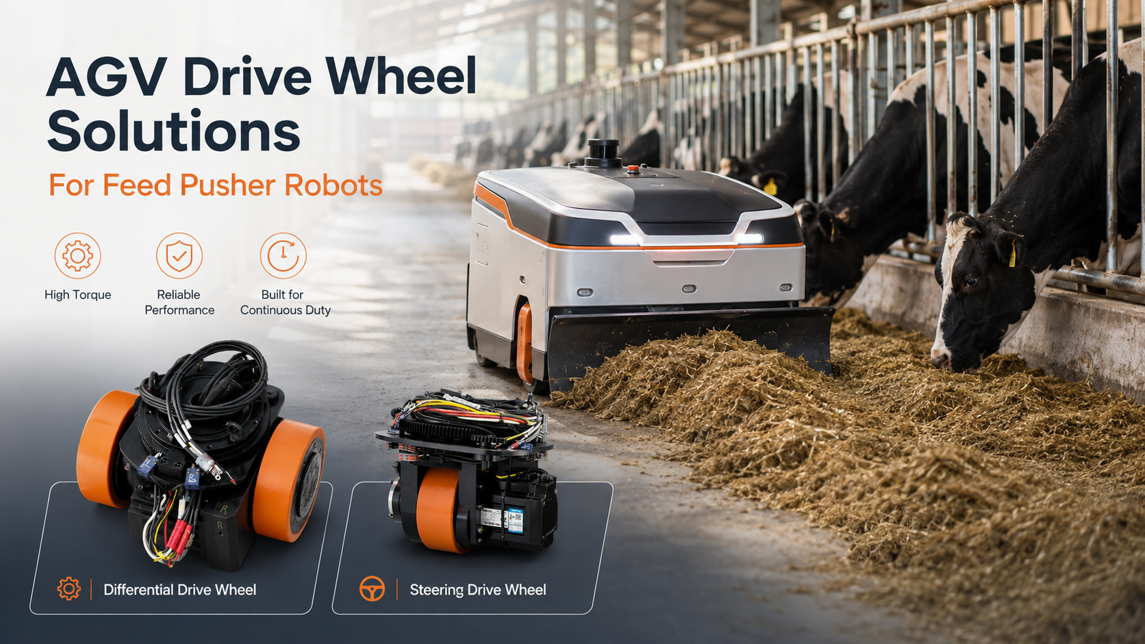
Yem itme robotları normal depo AGV'leri gibi çalışmaz.
Bir depo AGV'si genellikle temiz ve düz bir zeminde mal taşır. Bir yem itme robotu ise yemleme alanı boyunca hareket ederken sürekli olarak otu veya karma yemi hayvanlara doğru iter.
Normalde düşük hızda hareket eder ancak yine de yeterli itme kuvvetine ihtiyaç duyar. Zemin ayrıca ıslak, tozlu, düzensiz olabilir veya yem artıklarıyla kaplı olabilir.
Bu nedenle, tahrik tekerleklerini sadece robot ağırlığına göre seçmek yeterli değildir. Tekerlek yükü, çıkış torku, tekerlek çapı, tekerlek malzemesi, zemin durumu ve şasi yerleşimi bir bütün olarak değerlendirilmelidir.

Yem İtme Robotu Tekerleklerini Farklı Kılan Nedir?
Bir yem itme robotunun tahrik tekerlekleri, robotu desteklemeli ve yemi itmek için yeterli çekişi sağlamalıdır.
İtme direnci her zaman sabit değildir. İnce bir gevşek yem tabakasını hareket ettirmek nispeten kolaydır. Büyük veya sıkışmış bir yığın çok daha fazla kuvvet gerektirebilir. Çalışma sırasında robotun ayrıca şunları yapması gerekebilir:
-
Zaten yeme temas halindeyken harekete geçmek
-
Düşük hızda dengeli hareket etmek
-
Dar bir yemleme yolunda dönmek
-
Nemli veya kirli beton zeminlerde çalışmak
-
Küçük derzlerden, drenaj boşluklarından veya eşiklerden geçmek
-
Gün boyunca birkaç kez çalışmak
Bu, uygun bir tahrik tekerleğinin hem yeterli yük kapasitesi hem de yeterli kullanılabilir çekiş sağlaması gerektiği anlamına gelir. Yüksek yük değerine sahip bir tekerlek, torku çok düşükse veya zemin üzerinde kayıyorsa yine de uygun olmayabilir.
Diferansiyel Tahrikli Tekerlekler mi yoksa Yönlendirilebilir Tahrikli Tekerlekler mi?
İlk adım temel tahrik düzenini seçmektir.
Çoğu kompakt yem itme robotu, diferansiyel tahrikli tekerlekleri veya yönlendirilebilir tahrikli tekerlekleri kullanabilir. Doğru seçim; şasi şekline, gerekli harekete, mevcut alana ve bütçeye bağlıdır.
Diferansiyel Tahrikli Tekerlekler
Diferansiyel bir tahrik sistemi normalde biri solda diğeri sağda olmak üzere iki tahrik tekerleği kullanır.
İki tekerlek bağımsız olarak kontrol edilir. Aynı hızda döndüklerinde robot düz ilerler. Farklı hızlarda döndüklerinde robot döner. Zıt yönlerde döndüklerinde ise robot kendi merkezi etrafında dönebilir.
Diferansiyel tahrikli tekerlekler genellikle şunlar için uygundur:
-
Yuvarlak veya kompakt yem itme robotları
-
Sabit yemleme rotaları
-
Dar ahır koridorları
-
Olduğu yerde dönmesi gereken robotlar
-
Düşük profilli şasiler
-
Daha basit bir tahrik yapısına ihtiyaç duyan projeler
Bu düzen kompakt ve entegre edilmesi nispeten kolaydır. Ancak her iki tahrik tekerleği de zeminle iyi temas halinde kalmalıdır. Şasi dengeli değilse, tekerleklerden biri daha az yük taşıyabilir ve çekiş gücünü kaybedebilir.
Bu nedenle tahrik tekerlekleri, sarhoş tekerlekler, batarya konumu ve yem itme yapısı bir arada değerlendirilmelidir.

Yönlendirilebilir Tahrikli Tekerlekler
Yönlendirilebilir bir tahrik tekerleği, sürüş ve yönlendirmeyi tek bir ünitede birleştirir. Şunlar için yararlı olabilir:
-
Daha büyük yem itme robotları
-
Dikdörtgen şasiler
-
Daha ağır tarım robotları
-
Daha karmaşık seyahat rotaları
-
Farklı ahır alanları arasında hareket eden robotlar
-
Esnek konumlandırma gerektiren uygulamalar
Yönlendirilebilir bir tahrik tekerleği normalde diferansiyel tahrikli bir tekerlekten daha fazla kurulum alanı gerektirir. Kontrol ve mekanik yapısı da daha karmaşıktır.
Kompakt bir yuvarlak yem itme robotu için genellikle değerlendirilmesi gereken ilk seçenek diferansiyel tahriktir. Daha büyük veya daha esnek bir tarımsal AGV için yönlendirilebilir tahrikli tekerlekler daha uygun olabilir.

Düşük Hız Torku Neden Önemlidir?
Yem itme robotları normalde yavaş hareket eder ancak düşük hız, düşük güç anlamına gelmez.
Robot, yem ön plakaya, dönen tambura veya itme eteğine doğru baskı yaparken hareket etmeye devam etmelidir.
Gerekli tekerlek torku; yem miktarına, yem yoğunluğuna, itme yapısına, robot ağırlığına, tekerlek çapına, zemin sürtünmesine, eğime, dişli oranına ve dişli kutusu verimliliğine bağlıdır.
Daha yüksek bir redüksiyon oranı, tekerlekte daha fazla çıkış torku sağlayabilir. Ancak bu aynı zamanda maksimum seyahat hızını da düşürür. Bu nedenle motor, dişli kutusu ve tahrik tekerleği tek bir komple ünite olarak seçilmelidir.
Dişli oranını ve tekerlek çapını kontrol etmeden daha büyük bir motor seçmek sorunu çözmeyebilir.
Bazı durumlarda, aşırı çıkış torku tekerleğin ıslak bir zeminde patinaj yapmasına neden olabilir. Hedef, mevcut çekişi aşmadan yeterli torku sağlamaktır.
Tekerlek Çapı Yem İtme AGV'lerinin Performansını Nasıl Etkiler?
Tekerlek çapı; torku, hızı, şasi yüksekliğini ve engel aşma yeteneğini etkiler.
|
Tekerlek Boyutu
|
Avantajlar
|
Sınırlamalar
|
|
Büyük Tekerlekler
|
-Düzensiz beton ve küçük yükseklik farklarıyla başa çıkar; -Pürüzlü zeminlerde daha yumuşak hareket eder; |
-Aynı itme kuvveti için daha fazla çıkış torku gerektirir;
-Daha fazla şasi alanı kaplar, kurulum yüksekliğini artırır;
|
|
Küçük Tekerlekler
|
-Düşük şasi tasarımına olanak tanır;
-Sınırlı kurulum alanına sığar;
-Kompakt tahrik üniteleri için uygundur;
-Sınırlı torktan güçlü zemin kuvveti sağlar;
|
-Boşluklardan, eşiklerden ve düzensiz zeminlerden daha fazla etkilenir;
-Pürüzlü yüzeylerde daha az pürüzsüz hareket eder;
|
Bir tekerleği sadece şasi çizimine uyduğu için seçmeyin. Doğru tekerlek çapı, hem gerekli itme kuvvetine hem de gerçek ahır zeminine göre seçilmelidir. Daha büyük tekerlekler engel aşmayı ve hareketi pürüzsüzleştirmeyi iyileştirir ancak daha fazla tork ve alan talep eder. Daha küçük tekerlekler alandan tasarruf sağlar ve düşük profillere olanak tanır ancak zemin düzensizliklerine karşı daha hassastır.
Tekerlek Malzemesini Seçmek
Bir hayvancılık ahırındaki zemin ıslak, tozlu veya yem artıklarıyla kaplı olabilir. Bu, tekerlek malzemesini özellikle önemli kılar.
Poliüretan Tekerlekler
Poliüretan, AGV tahrik tekerlekleri için yaygın olarak kullanılır. Temel avantajları arasında iyi aşınma direnci, sabit yük kapasitesi, düşük yuvarlanma direnci, uygun zeminlerde uzun hizmet ömrü ve nispeten düşük gürültü yer alır.
Ancak pürüzsüz bir poliüretan tekerlek, her ıslak veya kirli zeminde yeterli tutuş sağlamayabilir.
Sertlik ve yüzey deseni uygulamaya göre seçilmelidir.
Kauçuk Tekerlekler
Kauçuk tekerlekler, belirli ıslak zeminlerde daha iyi tutuş, üstün titreşim emilimi, düzensiz yüzeylerde daha pürüzsüz hareket ve daha düşük çalışma gürültüsü dahil olmak üzere birçok fonksiyonel fayda sağlar.
Ancak kauçuk, yük altında daha fazla deforme olabilir ve bazı uygulamalarda daha hızlı aşınabilir.
Yük kapasitesi, hizmet ömrü ve yuvarlanma direnci seçimden önce kontrol edilmelidir.
Özel Dişli veya Tekerlek Yüzeyi
HKT ROBOT'ta, özel ahır koşulları için tekerlek yüzeyi bazen özelleştirilebilir.
Bir diş deseni, su veya yem artığı olan zeminlerde tutuşu iyileştirebilir. Ancak bu aynı zamanda yuvarlanma direncini, titreşimi veya aşınmayı da artırabilir.
Her yem itme robotu için uygun tek bir tekerlek malzemesi yoktur. Tekerlek malzemesini ve sertliğini seçmeden önce zemin fotoğrafları veya videoları sağlamak faydalıdır.
AGV Tahrik Tekerleklerini Seçerken Önemli Hususlar
Bir yem itme robotu için AGV tahrik tekerleklerini seçmek sadece toplam robot ağırlığını kontrol etmekle ilgili değildir. İtme yükü, şasi tasarımı, ahır zemini ve günlük çalışma süresi nihai seçimi etkileyebilir.
Tekerlek Yükü ve Ağırlık Dağılımı
İki robot aynı toplam ağırlığa sahip olsa da çok farklı tahrik tekerlekleri gerektirebilir. Sadece düz bir zeminde ilerleyen bir robot, sürekli olarak büyük bir yem yığınını iten bir robotla aynı dirençle karşılaşmaz.
Her tahrik tekerleği üzerindeki yük şunlara bağlıdır:
-
Toplam robot ağırlığı
-
Şasi yerleşimi
-
Batarya ve motor konumu
-
İtme yapısı
-
Tahrik tekerleklerinin sayısı ve konumu
-
Ağırlık merkezi
-
Gerekli güvenlik faktörü
Tekerlek yükü her zaman toplam ağırlığın tekerlek sayısına bölünmesiyle hesaplanmamalıdır.
Batarya, sensörler, itme plakası ve diğer bileşenler bir tarafın veya bir aksın daha fazla ağırlık taşımasına neden olabilir. Robotun önündeki itme kuvveti de çalışma sırasında yük dağılımını değiştirebilir.
Her iki tahrik tekerleği de yeterli ve makul düzeyde dengelenmiş dikey yük taşımalıdır. Aksi takdirde, motor yeterli tork sağladığında bile bir tekerlek tutuşunu kaybedebilir.
Çekiş ve Tekerlek Kayması
Tekerlek kayması, özellikle ıslak veya kirli ahır zeminlerinde yem itme uygulamalarında yaygın bir sorundur.
Daha fazla motor torku her zaman daha fazla kullanılabilir itme kuvveti oluşturmaz. Tekerlek çekişini kaybettiğinde, ek tork esas olarak boşa dönmesine neden olur.
Tekerlek patinajı; tahrik tekerlekleri üzerindeki ağırlığın yetersiz olması, kötü şasi ağırlık dağılımı, uygun olmayan tekerlek malzemesi veya sertliği, ıslak zeminler veya yem artıkları, aşırı çıkış torku, iki tahrik tekerleği arasındaki dengesiz temas, tahrik tekerlekleri üzerindeki yükü azaltan bir itme yapısı veya bir tekerleğin düz olmayan bir zemin bölümünden geçmesi nedeniyle oluşabilir.
Çekişi iyileştirmek için robot tasarımcısının tahrik tekerleği konumunu, batarya konumunu, ağırlık merkezini, tekerlek genişliğini, diş yapısını veya süspansiyon yapısını ayarlaması gerekebilir.
Daha güçlü bir motor, tahrik tekerleklerini zemine sıkıca bastırmayan bir şasiyi telafi edemez.
Zemin Engelleri ve Tekerlek Düzeni
Hayvancılık ahırları zemin birleşim yerleri, drenaj kanalları, küçük eşikler, eğimler ve farklı alanlar arasındaki yükseklik farklarını içerebilir.
Tekerlek çapını seçmeden önce şunları doğrulamak önemlidir:
-
Maksimum eşik yüksekliği
-
Maksimum drenaj boşluğu genişliği
-
Zemin birleşim yeri genişliği
-
Maksimum eğim
-
Gerekli yerden yükseklik
-
Döner tekerlek (caster) çapı
-
Şasi yaklaşma açısı
Daha büyük tahrik tekerlekleri genellikle küçük engelleri daha kolay geçer ancak daha fazla tork ve kurulum alanına ihtiyaç duyarlar.
Bu nedenle, yalnızca motorlu tekerlekler değil, tüm tekerlek düzeni gözden geçirilmelidir.
Günlük Çalışma Döngüsü
Yem itme robotları genellikle günde birkaç kez çalışır. Bazıları her döngüde sadece birkaç dakika çalışırken, diğerleri büyük ahırlarda daha uzun süre çalışır.
Gerçek çalışma döngüsü motor ve şanzıman sıcaklığını, yatak ömrünü, tekerlek aşınmasını, batarya tüketimini ve bakım aralıklarını etkiler; bu nedenle müşteriler döngü başına çalışma süresini, günlük döngü sayısını, ortalama itme süresini, maksimum sürekli çalışma süresini ve döngüler arasındaki dinlenme süresini bildirmelidir.
Bir tahrik tekerleği kısa bir prototip testi sırasında iyi performans gösterebilir ancak günlük operasyon sırasında aşırı ısınabilir veya çok çabuk aşınabilir.
Bu nedenle, tahrik tekerleği sadece maksimum yüküne ve hızına göre değil, robotun gerçek çalışma programına göre seçilmelidir.
Yem İtme Robotu Tahrik Tekerlekleri İçin Neden HKT ROBOT'u Seçmelisiniz?
HKT ROBOT, 2013 yılından beri AGV ve AMR tahrik sistemlerine odaklanmıştır. Farklı mobil robot platformları için diferansiyel tahrik tekerlekleri, direksiyonlu tahrik tekerlekleri, servo motorlar, şanzımanlar, sürücüler ve ilgili hareket bileşenleri tedarik etmekteyiz.
Yem itme robotu projeleri için sadece nominal yüküne dayalı bir tekerlek önermiyoruz. Ekibimiz, uygun bir çözüm önermeden önce robot ağırlığını, itme kuvvetini, tekerlek çapını, ahır zeminini, günlük çalışma döngüsünü ve kurulum düzenini gözden geçirir. Daha hızlı entegrasyon için standart ürünler mevcut olmakla birlikte, uygulama gerektirdiğinde tekerlek malzemesi, dişli oranı, motor gücü ve montaj arayüzleri de özelleştirilebilir.
Tarımsal yem itme uygulamalarındaki pratik deneyimimiz, uzman mühendislik ekibimiz, iki yıllık garantimiz ve 24 saat teknik desteğimizle, müşterilerimizi ilk tahrik tekerleği seçiminden prototip testine ve sonraki üretime kadar destekleyebiliyoruz.
Otonom bir yem itme robotu veya başka bir hayvancılık mobil robotu geliştiriyorsanız, şasi çiziminizi ve çalışma gereksinimlerinizi bize gönderin. Güvenilir itiş ve istikrarlı hareket için doğru AGV tahrik tekerleklerini seçmenize yardımcı olalım.
Paylaşmak:
AGV Servo Motor Devreye Alma: Yaygın Kurulum ve Ayar Sorunları
Bir AGV Servo Sürücüsü Ne Yapar? Sürücüyü İnsan Vücudu Üzerinden Anlamak