7*24 Saat Destek ve Tam Sürücü Sistemi Çözümleri

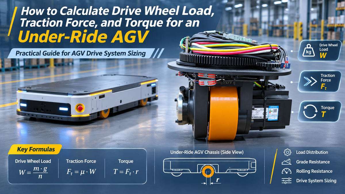
Under-ride AGVs are widely used in smart warehouses, factory logistics, and automated production lines.
Compared with standard AGVs, under-ride AGVs usually have a lower chassis, limited installation space, and changing load conditions. This puts more demand on the drive wheels. They need to support the required load and provide enough traction to keep the vehicle running smoothly, especially during full-load starts and uphill movement.
In real projects, choosing AGV drive wheels based only on rated load or motor power can lead to several problems such as:
  • The drive wheels may slip when starting with a full load.
  • Insufficient wheel load can reduce traction and affect driving performance.
  • The motor may not provide enough torque during acceleration.
So, selecting drive wheels for a latent AGV involves more than checking the rated load. Total vehicle weight, drive wheel load, rolling resistance, ground adhesion, and target acceleration all need to be considered.
In this article, we'll look at how to calculate AGV drive wheel load, traction force, and acceleration. We'll also use an example to show how these calculations work in practice.

1. Understanding the Load of an Under-Ride AGV

The first step in AGV drive system calculations is to determine the total vehicle mass.
For a lifting-type under-ride AGV, the weight of the rack and cargo must be included if they are lifted and carried together with the vehicle.
The total vehicle mass is:  
Mtotal = mAGV + mload

Where:

  • mAGV: AGV body mass (kg)
  • mload: Mass of the rack and cargo carried by the AGV (kg)
  • Mtotal: Total vehicle mass (kg)
The total weight is:
                                                                   W = M × g
Here, g is the gravitational acceleration, taken as 9.81 m/s².
One thing to keep in mind: if the AGV only pushes a cart and the cart's own wheels remain on the ground, the cart's entire mass should not be treated as a load supported by the AGV drive wheels. In this case, the cart's rolling resistance needs to be calculated separately.

2. Load Distribution on Under-Ride AGV Drive Wheels

Drive wheel load is one of the key factors affecting AGV traction.
Under-ride AGVs often use drive wheels together with caster wheels or other support wheels. The vehicle's weight is shared by these contact points. It should not be assumed that the drive wheels carry an equal share of the total vehicle weight.
Actual load distribution depends on several factors:
  • The mounting positions of the drive wheels and support wheels.
  • The center of gravity of the AGV and its cargo.
  • The design of the lifting mechanism.
  • The drive wheel suspension and spring preload.
  • Changes in load under empty, full-load, and uneven-load conditions.

2.1 Actual Load on the Drive Wheels

For an initial estimate, the total normal load on the drive wheels can be calculated using the percentage of vehicle weight they support:

Nd = λ × Mtotal × g

Where:

  • Nd: Total normal load on all drive wheels (N)
  • λ: Proportion of the total vehicle weight supported by the drive wheels (e.g., 0.5 for 50%)
  • Mtotal: Total vehicle mass (kg)
  • g: Gravitational acceleration (9.81 m/s²)

Example:

An AGV has a total mass of 800 kg, and its two drive wheels support 50% of the vehicle weight.

Nd = 0.5 × 800 × 9.81

                                                        = 3,924 N

If the two drive wheels share the load equally, each wheel supports approximately 1962 N.
The 50% figure is only an assumption for this example. It is not a standard value for all AGVs. The actual load ratio depends on the chassis design, center of gravity, and suspension structure.

2.2 Drive Wheel Pressure

Some under-ride AGVs use spring-loaded or floating suspension systems to keep the drive wheels in contact with the floor.
If the pressure is too low, the wheels may slip. If it is too high, it can increase wheel wear, bearing loads, and running resistance.
The actual drive wheel load should therefore be checked under empty, full-load, and uneven-load conditions.
For drive wheels with spring-loaded mechanisms, the spring stiffness, preload, and mounting structure should also be considered.
It's important to understand the difference between rated load and actual normal load. Rated load refers to how much weight the drive wheel structure can support. Actual normal load affects how much traction the wheel can transfer to the floor.

3. AGV Running Resistance and Traction Force Calculation

Once the total vehicle mass is known, the next step is to calculate the resistance the AGV needs to overcome.
For an indoor, low-speed under-ride AGV, the main factors are rolling resistance, slope resistance, and acceleration force.

3.1 Rolling Resistance

Rolling resistance mainly comes from wheel deformation when the wheel contacts the floor, as well as mechanical losses in the wheels and bearings.
The formula is:

                                Fr = Crr × Mtotal × g × cos(θ)

Where:

  • Fr: Rolling resistance (N)
  • Crr: Rolling resistance coefficient
  • Mtotal: Total vehicle mass (kg)
  • g: Gravitational acceleration (9.81 m/s²)
  • θ: Slope angle

On a flat floor (θ = 0°), the formula becomes:

                                       Fr = Crr × Mtotal × g

The rolling resistance coefficient is not a fixed value. It depends on factors such as polyurethane wheel hardness, wheel diameter, floor material, surface condition, and actual load.
For a real project, it's better to use test data from the drive wheel supplier or measure the resistance through a full-load test.

3.2 Slope Resistance

When an AGV travels uphill, it needs extra traction to overcome the force of gravity acting along the slope.
The formula is:

                                       Fg = M × g × sin(θ)

Where θ is the slope angle.
A 3% gradient means a 3-meter height difference over every 100 meters of horizontal distance. It does not mean a 3-degree slope.
For under-ride AGVs, it's also worth checking transitions around lifting platforms, floor joints, and uneven surfaces. These conditions can affect the actual driving resistance.

3.3 Acceleration Force

When an AGV starts or speeds up, it needs extra driving force to overcome the inertia of the vehicle.
According to Newton's second law, acceleration force depends on the total vehicle mass and target acceleration.
The formula is:

Fa = M × a

Where:

  • Fa: Acceleration force (N)
  • M: Total vehicle mass (kg)
  • a: Target acceleration (m/s²)

Example:

An AGV with a total mass of 800 kg and a target acceleration of 0.3 m/s² requires:

                                             Fa = 800 × 0.3 = 240 N

A higher acceleration requires more traction from the drive system.
This is a simplified calculation. It does not include the rotational inertia of the motor rotor, wheels, or gearbox. For systems with high acceleration or heavy loads, these factors should also be checked.

3.4 Total Traction Force

The total traction force is the sum of rolling resistance, slope resistance, and acceleration force.

Ftotal = Fr + Fg + Fa

The Full Formula:

                         Ftotal = M × a + Crr × M × g × cos(θ) + M × g × sin(θ)

This is the main formula used when calculating the traction force required by an under-ride AGV.
On a flat floor, the slope resistance is zero, so the calculation becomes simpler.
For indoor AGVs running at low speeds, air resistance is usually small enough to ignore. For outdoor or high-speed applications, it may need to be included.

4. AGV Drive Wheel Traction and Output Torque

After calculating the total traction force, the next step is to determine how much force each drive wheel needs to provide and how much output torque is required.

4.1 Traction Force Per Drive Wheel

Assume the AGV uses two drive wheels and both wheels share the traction force equally.

Fwheel = Ftotal / n

Where:

  • Fwheel: Traction force required from each drive wheel (N)
  • Ftotal: Total vehicle traction force (N)
  • n: Number of drive wheels
For example, if the total traction force is 600 N and the AGV has two drive wheels, each wheel needs to provide 300 N.
In practice, traction force may not be shared equally between multiple drive wheels. If wheel loads or control outputs are different, each wheel should be checked separately.

4.2 Drive Wheel Output Torque

The drive wheel converts motor torque into traction force at the floor.
The required output torque for each drive wheel is:

Twheel = (Ftotal × r) / n

Where:

  • Twheel: Output torque of one drive wheel (N·m)
  • r: Effective rolling radius of the drive wheel (m)
  • n: Number of drive wheels
With all other conditions unchanged, a larger wheel radius requires more output torque to produce the same traction force.

4.3 Matching the Motor and Gearbox

Most AGV drive systems use a servo motor together with a gearbox.
The gearbox reduces motor speed and increases output torque. The required motor shaft torque can be estimated from the drive wheel output torque, gear ratio, and transmission efficiency.
             Motor torque = Drive wheel output torque / (Gear ratio × Transmission efficiency)
However, this is only the theoretical torque requirement. The motor's rated torque, peak torque, operating speed, and continuous operating capacity must also be checked.
For AGVs that start frequently or operate under full load for long periods, choosing a motor based only on peak torque is not enough.

5. Drive Wheel Adhesion and Slip Prevention

This is an important point that is sometimes overlooked when designing an under-ride AGV drive system.
Having enough motor torque does not always mean the drive wheels can transfer that torque to the floor.
If the drive wheels do not have enough pressure against the ground, they may slip even when the motor can deliver sufficient torque.
The maximum available traction force depends on the ground adhesion coefficient and the normal load on the drive wheels.

Fadhesion = μ × Nd

Where:

  • Fadhesion: Maximum available traction force (N)
  • μ: Ground adhesion coefficient
  • Nd: Total normal load on the drive wheels (N)

To prevent wheel slip, the following conditions must be met:

                                      Ftotal ≤ Fadhesion

If the AGV has several drive wheels or uneven load distribution, each drive wheel should also be checked separately.
Keep in mind that the rolling resistance coefficient and the ground adhesion coefficient are two different values. They should not be used interchangeably.
For polyurethane drive wheels, actual adhesion depends on floor material, oil or water contamination, wheel hardness, and surface condition. Testing on the actual floor is the best way to confirm performance.

6. Engineering Example: Drive Wheel Calculation for an 800 kg Under-Ride AGV

Let's take an under-ride AGV with a total mass of 800 kg and two drive wheels as an example.
Assume the drive wheel diameter is 160 mm, the rolling resistance coefficient is 0.02, the maximum slope is 3%, and the target acceleration is 0.3 m/s². The gear ratio is 20:1, and the gearbox efficiency is 90%. We also assume that the two drive wheels support 50% of the total vehicle weight, with a ground adhesion coefficient of 0.25.
First, calculate the resistance and acceleration force.
The rolling resistance is:

                                           Fr = 0.02 × 800 × 9.81 × cos(1.72°) ≈ 156.89 N

The slope resistance is:

                                             Fg = 800 × 9.81 × sin(1.72°) ≈ 235.33 N

The acceleration force is:

                                            Fa = 800 × 0.3 = 240 N

Therefore, the total traction force required is:

                                   Ftotal = 156.89 + 235.33 + 240 = 632.22 N

Since the AGV has two drive wheels, each wheel needs to provide approximately 316.11 N of traction force.

With a wheel radius of 0.08 m, the required output torque per drive wheel is:

                                    Twheel = 316.11 × 0.08 ≈ 25.29 N·m

Based on a 20:1 gear ratio and 90% transmission efficiency, the required motor shaft torque is:

                                     Tmotor = 25.29 / (20 × 0.9) ≈ 1.405 N·m

Next, check whether the drive wheels have enough grip. If the two drive wheels support 50% of the total vehicle weight, their combined normal load is approximately 3,924 N.

With an assumed ground adhesion coefficient of 0.25, the maximum available traction force is:

                                       Fadhesion = 0.25 × 3,924 = 981 N

Since 981 N is greater than the required 632.22 N, the drive wheels have enough theoretical adhesion under these assumed conditions. The traction utilization is approximately 64.5%.
Calculation result: Each drive wheel needs to provide approximately 316.11 N of traction force and 25.29 N·m of output torque. Each motor requires approximately 1.405 N·m of shaft torque under this simplified model.
These figures are for initial sizing only. Actual motor selection should also consider peak torque, rated torque, operating speed, rotational inertia, uneven wheel loads, and real floor conditions. The assumed load distribution, rolling resistance, and adhesion coefficient should also be verified through actual testing.

7. Key Factors to Consider When Selecting Under-Ride AGV Drive Wheels

After completing the calculations, the drive system still needs to be checked against actual operating conditions.

7.1 Don't Look at Rated Load Alone

The rated load mainly shows how much weight the drive wheel structure can support. Traction also depends on the actual normal load and ground adhesion coefficient.
Both need to be checked.

7.2 Consider Empty, Full-Load, and Uneven-Load Conditions

When an under-ride AGV lifts a rack, the center of gravity and drive wheel load may change.
This is especially important when the cargo is not evenly distributed. The drive wheels must still have enough contact pressure to provide the required traction.

7.3 Match Torque and Travel Speed

A higher gear ratio usually increases output torque but reduces drive wheel speed.
The gear ratio, wheel diameter, motor speed, and target AGV speed need to work together. Choosing a larger torque rating alone does not guarantee better performance.

7.4 Check the Motor's Continuous Operating Capacity

A motor may provide enough peak torque for a short time, but that does not mean it can maintain the same torque continuously.
For AGVs that operate for long hours or start and stop frequently, the temperature rise of the motor, gearbox, and servo drive should also be checked.

7.5 Check Braking and Slope Holding Separately

Driving performance and braking performance are two different requirements.
An AGV must be able to stop safely on a slope under full load. It may also need to hold its position when the power is off.
The holding torque of the electromagnetic brake, gearbox transmission ratio, and actual slope conditions all need to be checked separately. Motor driving torque alone cannot confirm whether the braking system is sufficient.

8. HKT ROBOT: Your Go-To AGV Drive Wheels & Motion Solutions Partner

Selecting drive wheels for an under-ride AGV is not simply about choosing a product with a high enough rated load.
Founded in 2013, HKT ROBTO brings over 10 years of expertise in manufacturing and delivering core agv components for agv/amr motion and control, from agv steering drive wheels and differential drive unit to servo dirve and agv lifting mechanism.
For agv drive wheel projects, we do not just provide agv drive wheels; We provide the corresponding and suitable solutions, too. We evaluate the vehicle's total mass, maximum payload, target speed, number of drive wheels, and available installation space. Based on these details, we can help select a suitable wheel diameter, gear ratio, motor power, and drive configuration.
Moreover, we can support customization based on project requirements.

If you are developing a new under-ride AGV or AMR, you can share related information with us. Our sales and engineering team can help evaluate suitable drive wheels and motion control solutions.
 

Disclaimer & Safety Notice
The formulas, assumed parameters, and calculation results in this article are provided for preliminary sizing and concept comparison of under-ride AGV drive systems only. They do not constitute a final engineering design, product specification, warranty statement, or safety certification.
Actual drive wheel and motor selection must consider vehicle center of gravity, load transfer, unloaded/full-load/off-center loading conditions, rotational inertia, floor material and contamination, ramp and parking requirements, braking performance, motor and gearbox thermal behavior, ingress protection, and applicable safety standards. Final designs should be validated through full-load, ramp, frequent start-stop, and real-floor testing.
For projects involving personnel safety, regulatory compliance, brake holding, emergency stop, or mass production, the final design should be reviewed by qualified engineers in accordance with the relevant vehicle design standards.